• Jeśli chcesz dodać swojej Alfie charakteru i jednocześnie zaznaczyć przynależność do naszej społeczności – to dobry moment, żeby je zamówić.

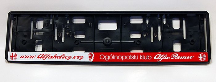
    Ramki Alfaholicy

    Szczegóły, zdjęcia oraz informacje o zamówieniu znajdziesz tutaj.

    Nie czekaj, bo jak zwykle schodzą szybko.

Little modification (start/stop engine)

metan

New
Joined
Jul 16, 2009
Messages
1,113
Location
K-ce
Car
Mito 1,4 MPI
In a moment of boredom/inspiration I did something like this:


The button is from the 159/Brera, admittedly it doesn't completely replace the key (although that could be arranged but giving up the mechanical steering lock), but it somehow makes starting more convenient. The button controls the electronic module that starts/stops the engine.
The red ring lights up when the engine is off, the on/off inscription is tied to the dashboard lighting (BTW interesting how it is in the original because the power for the ring and the inscription is separate).
 
Last edited:
I’m impatiently waiting for you to install a catapult into the Mićak (Miata?). I can lend a few Bond cars (I have all of them) for inspiration :D.
 
In a moment of boredom/inspiration I did something like this:


The button is from the 159/Brera, admittedly it doesn't completely replace the key (although that could be arranged but giving up the mechanical steering lock), but it somehow makes starting more convenient. The button controls the electronic module that starts/stops the engine.
The red ring lights up when the engine is off, the on/off inscription is tied to the dashboard illumination (BTW interesting how it is in the original because the power supply for the ring and the inscription is separate).


provide some manual how to do this :D
 
provide some manual how to do this :D
I would prefer concrete questions because different people may have doubts about different issues.
You need to buy a button from the 159 at a decent price, I don’t have a description of the terminals with me; once someone decides I’ll look for it. As a connector it fits, for example, a piece of tape from a hard drive, unless someone has the original loom or whatever fits with a 2.5 mm raster.
Mounting in the hole is a manual task—the tunnel is simply pulled up. You need to cut a hole; to mount such a button (it’s quite large) you have to grind a little from the bottom of one plastic latch on the tunnel. Other buttons (there are plenty from Meganes but that’s not this family :D they can be smaller). This button cannot be wired live to the ignition (even to starting) because it’s on rubber mounts and at crank of 8 amps current flows there, plus other things must be arranged, so required electronics.
The module must operate according to the logic that when the engine is running it cuts the power through one of the relays in the engine bay to stop it, if it’s not running shorts the contacts that ignition shorts at starting. The trouble is I didn’t memorize the colors (everything is already insulated and assembled), but you can measure it without a problem. At the same time some contacts of certain receivers must be drilled out (analogous to the ignition). And now the most precise part—the working state signal is taken from the charging lamp, and since it’s triggered digitally over CAN and there’s no wire from the voltage regulator (at least I didn’t find one) you have to solder into one path at the back of the instrument cluster, so you have to detach it. Of course everything with more care than the pasta makers in the factory :).
BTW identical stepper motors are in instrument clusters in Citroëns from over 10 years ago and the construction is very similar—same VDO manufacturer).
To avoid interference and to be 100% sure I didn’t use ICs or a microcontroller; I implemented everything with a few transistors and three relays. Also you must consider that after pressing the button and starting the engine, when the charging signal appears and the button is still pressed the module won’t shut off the engine and then won’t start again, and so on in a loop. The backlighting of the button is a minor detail (you could even do two-tone by taking it apart, but I turned it on too late).
If someone decides, I’ll tell what and how (pity I didn’t photograph it, but it was cold).
 
Last edited:
I would prefer concrete questions because different people may have doubts about different issues.
You need to buy a button from the 159 at a decent price, I don’t have a description of the terminals with me; once someone decides I’ll look for it. As a connector it fits, for example, a piece of tape from a hard drive, unless someone has the original loom or anything that fits with a 2.5 mm raster.
Mounting in the hole is a manual task—the tunnel is simply pulled up by pulling it up. You need to cut a hole; to mount such a button (it’s quite large) you have to grind a latch on the tunnel from the bottom a bit. Other buttons (e.g., many from Meganes but not this family :D they can be smaller). You cannot wire this button directly to the ignition (even to starting) because it’s on rubbers and during starting 8 amps flow there and other things must be arranged, so electronics are required.
The module that must work according to the logic that when the engine is running it cuts the supply through one of the relays in the engine compartment; if it’s not running it short-circuits the contacts that a starter would short. The problem is I didn’t memorize the colors (everything is insulated and assembled), but you can measure them without a problem. At the same time wires for some loads must also be opened (analogous to the ignition). And now the most precise part—the working state signal is taken from the charging lamp, and since it’s triggered digitally by CAN and there’s no wire from the voltage regulator (at least I didn’t find one) you have to solder into one track at the back of the instrument cluster, so you have to remove it. Of course everything with more care than the factory would use :).
BTW identical stepper motors are in instrument clusters in Citroëns from over 10 years ago and the construction is very similar—the same manufacturer VDO).
To avoid interference and to be 100% sure I didn’t use ICs or a microcontroller; I implemented everything with a few transistors and three relays. You must also consider that after pressing the button and starting the engine, when the charging signal appears and the button is still pressed the module does not cut off the engine and then does not engage again, and so on. The backlighting of the button is a small detail (one could even do two-color by taking it apart, but I turned it on too late). If someone decides, I’ll tell what and how (regrettably I didn’t photograph it but it was cold).

post more modifications with photos, then the manual will be clearer and there would be fewer potential questions ;)
 
So, to sum up I still have to use the key, so why do I need these buttons? Add some fingerprint reader to the set or something similar. ;-)
 
So, to sum up I still have to use the key, so why do I need these buttons? Add some fingerprint reader to the set or something similar. ;-)
I’d rather someone steal my key than my finger :D.
And seriously, for example you also have to insert the key into the slot (like Renault cards) in order to disable the steering lock electronically. It annoys me that when you want to turn off the engine (e.g., in a traffic jam when I sometimes switch off) it rolls back to the first position (stop), which results in turning off the radio, turning off drive mode if it’s on, lights going out (I know you can leave the ignition on), and wrestling with the latch. Once my car did a prank and stalled while descending the revs and coasting in neutral (albeit slowly but still). Trying to restart in such a state risks locking the steering column. And in case of anything, the button is always at hand. It is arranged so that when pulling away I press it almost automatically after releasing the handbrake. And I like symmetry—the lighter looks lonely by itself.
 
Amortyzatory
Back
Top