

To diagnose the lambda sensor you don’t need to connect to the computer right away. For this task, an ordinary digital multimeter is enough.
(-) connect to the battery clamp
(+) to the lambda sensor signal line (black)
The values we obtain should oscillate between 0-1 V; ideal operation is a voltage from 0.35 to 0.85 V, i.e., Lambda 1.001
In AR equipped with 3 lambda sensors, the first two should react quite vividly (max 1 second) oscillating between 0-1V, whereas the third, although it has the same working range 0-1V, may have a smaller change frequency and in some cases may appear only at the second decimal place. Readings around the middle of the scale, i.e., 0.5 V, are probably the most correct.
The 3-sensor plug is marked in the red circle By null at 2010-08-04
In this photo you can clearly see all the cables from the sensor
Photo by MariuszR1 Description of the individual wires
Black - signal
Gray - ground
Two whites - ground and feed for the heater
While measuring the sensor in operation you can also check the heater’s functionality
With the ignition off, disconnect the connector and connect an ohmmeter to the two white wires from the sensor. The resistance should be between 3-15 ohms
For certainty you can also measure the voltage supplied by the ECU to the sensor
With a voltmeter connect to the two white wires from the sensor and start the engine. The voltage should be 12 V
Since my computer is an ECU ME 7.3.1 EOBD, the sensor voltage is supplied intermittently with pulse-width modulation. On a cold engine the voltage range is 2 to 13 V and as the sensor warms up tends toward 0 V
You can also measure the voltage supplied from the ECU to the sensor
We connect to the black and gray wire and turn the ignition. The voltage should be in the range of 0.5 V
Here are my measurements for comparison
Sensor 1, connector from the battery, parameters change very quickly
idle 0.301-0.699 V
loaded 0.13-0.78 V
voltage between black and gray 0.43 V
heater resistance 10.4 Ohms
Sensor 2, connector to the left of the camshaft, parameters change very quickly
idle 0.27-0.69 V
loaded 0.1-0.8 V
voltage between black and gray 0.43 V
heater resistance 10.9 Ohms
Sensor 3, connector above the intake manifold, values change third decimal place
idle 0.436 V
loaded 0.442 V
voltage between black and gray 0.43 V
heater resistance 10.8 Ohms"

By null at 2010-08-04
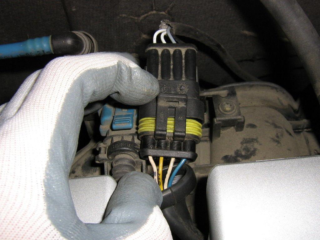
In this photo you can clearly see all the cables from the sensor
Photo by MariuszR1,
[center:e25162307b]
 [/center:e25162307b]
Description of the individual wires
Black - signal
Gray - ground
2 white - ground and power for the heater
While measuring the sensor operation you can also check the heater’s functionality
With the ignition off, disconnect the connector and insert an ohmmeter into the two white wires from the sensor. The resistance should be between 3-15 ohms
For certainty you can also measure the voltage supplied by the ECU to the sensor
With a voltmeter connect to the two white wires from the sensor and start the engine. The voltage should be 12 V
Since my computer is an ECU ME 7.3.1 EOBD, the sensor voltage is supplied intermittently with PWM modulation. On a cold engine the voltage values range from 2 to 13 V and as the sensor warms up the values approach 0 V
You can also measure the voltage supplied by the ECU to the sensor
We connect to the black and gray wire and turn the ignition. The voltage should be within 0.5 V
Here are my measurements for comparison
Sensor 1 connector from the battery, parameters change very quickly
idle 0.301-0.699 V
load 0.13-0.78 V
voltage between black and gray 0.43 V
heater resistance 10.4 Ohms
Sensor 2 connector to the left of the timing, parameters change very quickly
idle 0.27-0.69 V
load 0.1-0.8 V
voltage between black and gray 0.43 V
heater resistance 10.9 Ohms
Sensor 3 connector above the intake manifold, values change on the 3rd decimal place
idle 0.436 V
load 0.442 V
voltage between black and gray 0.43 V
heater resistance 10.8 Ohms
(-) connect to the battery clamp
(+) to the lambda sensor signal line (black)
The values we obtain should oscillate between 0-1 V; ideal operation is a voltage from 0.35 to 0.85 V, i.e., Lambda 1.001
In AR equipped with 3 lambda sensors, the first two should react quite vividly (max 1 second) oscillating between 0-1V, whereas the third, although it has the same working range 0-1V, may have a smaller change frequency and in some cases may appear only at the second decimal place. Readings around the middle of the scale, i.e., 0.5 V, are probably the most correct.
The 3-sensor plug is marked in the red circle By null at 2010-08-04
In this photo you can clearly see all the cables from the sensor
Photo by MariuszR1 Description of the individual wires
Black - signal
Gray - ground
Two whites - ground and feed for the heater
While measuring the sensor in operation you can also check the heater’s functionality
With the ignition off, disconnect the connector and connect an ohmmeter to the two white wires from the sensor. The resistance should be between 3-15 ohms
For certainty you can also measure the voltage supplied by the ECU to the sensor
With a voltmeter connect to the two white wires from the sensor and start the engine. The voltage should be 12 V
Since my computer is an ECU ME 7.3.1 EOBD, the sensor voltage is supplied intermittently with pulse-width modulation. On a cold engine the voltage range is 2 to 13 V and as the sensor warms up tends toward 0 V
You can also measure the voltage supplied from the ECU to the sensor
We connect to the black and gray wire and turn the ignition. The voltage should be in the range of 0.5 V
Here are my measurements for comparison
Sensor 1, connector from the battery, parameters change very quickly
idle 0.301-0.699 V
loaded 0.13-0.78 V
voltage between black and gray 0.43 V
heater resistance 10.4 Ohms
Sensor 2, connector to the left of the camshaft, parameters change very quickly
idle 0.27-0.69 V
loaded 0.1-0.8 V
voltage between black and gray 0.43 V
heater resistance 10.9 Ohms
Sensor 3, connector above the intake manifold, values change third decimal place
idle 0.436 V
loaded 0.442 V
voltage between black and gray 0.43 V
heater resistance 10.8 Ohms"
By null at 2010-08-04
In this photo you can clearly see all the cables from the sensor
Photo by MariuszR1,
[center:e25162307b]
Description of the individual wires
Black - signal
Gray - ground
2 white - ground and power for the heater
While measuring the sensor operation you can also check the heater’s functionality
With the ignition off, disconnect the connector and insert an ohmmeter into the two white wires from the sensor. The resistance should be between 3-15 ohms
For certainty you can also measure the voltage supplied by the ECU to the sensor
With a voltmeter connect to the two white wires from the sensor and start the engine. The voltage should be 12 V
Since my computer is an ECU ME 7.3.1 EOBD, the sensor voltage is supplied intermittently with PWM modulation. On a cold engine the voltage values range from 2 to 13 V and as the sensor warms up the values approach 0 V
You can also measure the voltage supplied by the ECU to the sensor
We connect to the black and gray wire and turn the ignition. The voltage should be within 0.5 V
Here are my measurements for comparison
Sensor 1 connector from the battery, parameters change very quickly
idle 0.301-0.699 V
load 0.13-0.78 V
voltage between black and gray 0.43 V
heater resistance 10.4 Ohms
Sensor 2 connector to the left of the timing, parameters change very quickly
idle 0.27-0.69 V
load 0.1-0.8 V
voltage between black and gray 0.43 V
heater resistance 10.9 Ohms
Sensor 3 connector above the intake manifold, values change on the 3rd decimal place
idle 0.436 V
load 0.442 V
voltage between black and gray 0.43 V
heater resistance 10.8 Ohms
Last edited:
